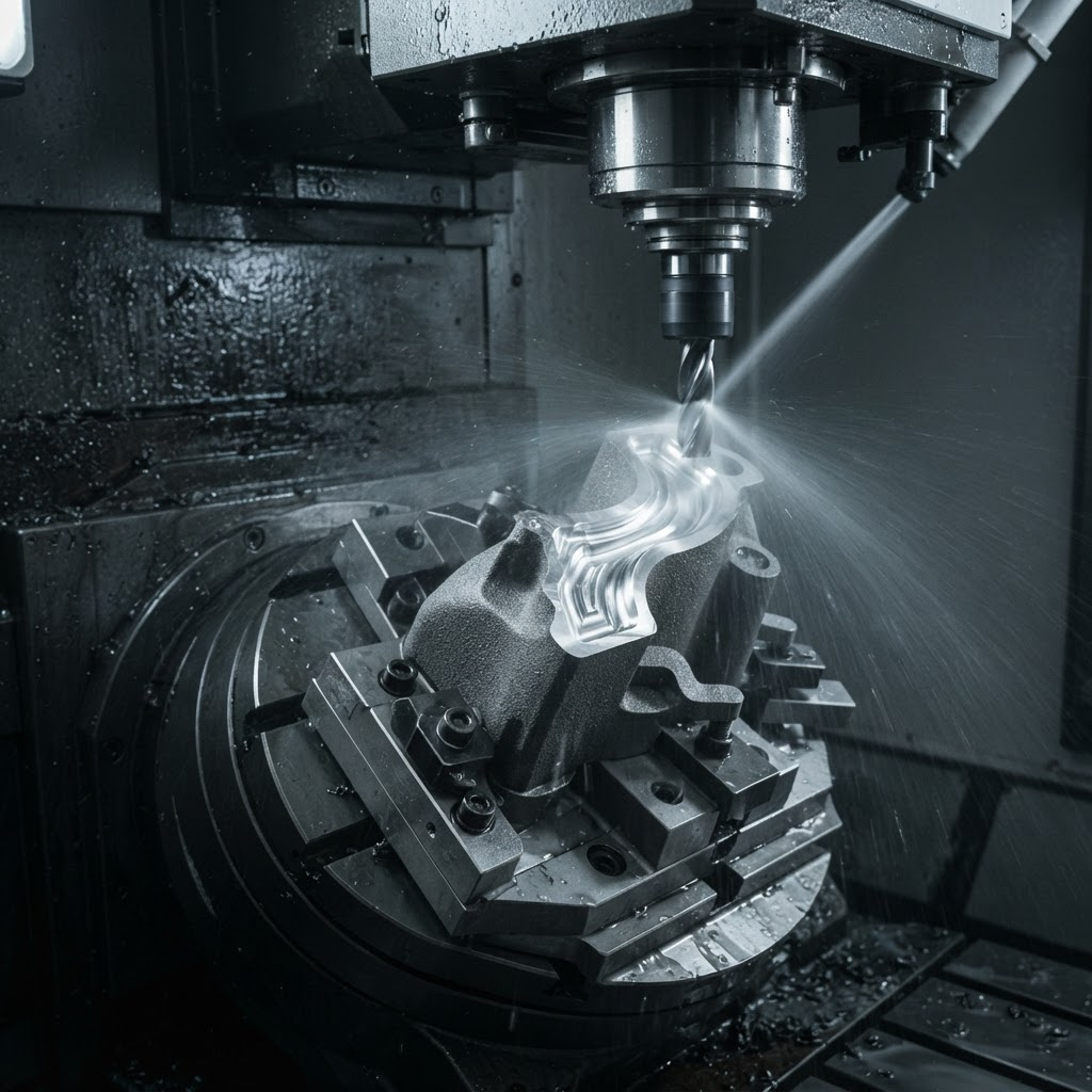
Capability
CNC machining and finishing.
Additive manufacturing produces the geometry. Machining produces the tolerance. Components that need both are handled in one place, with the interfaces between the two planned rather than negotiated afterwards.
Post-processing route
From build plate to finished component.
A printed part passes through a defined sequence. Each stage constrains the next.
- 01
Stress relief
Heat treatment to relieve residual stress from the build before the component is removed from the plate, preventing distortion during later operations.
- 02
Removal & support removal
Separation from the build plate and removal of support structures, with attention to the surface left behind on visible or functional faces.
- 03
Heat treatment
Solution treatment, ageing or hardening appropriate to the alloy and the specified mechanical properties.
- 04
Datum preparation
Machining the reference features that establish the coordinate frame for all subsequent operations and for inspection.
- 05
Precision machining
Milling, turning, reaming, threading and grinding of the features that require tolerances tighter than as-built capability.
- 06
Surface finishing
Blasting, tumbling, polishing or chemical treatment to reach the specified surface condition.
Machining services
Operations available in-house.
CNC milling
Faces, pockets, profiles and datum features to drawing.
CNC turning
Concentric features, diameters, seats and sealing faces.
Drilling
Accurate hole position, size and depth.
Thread machining
Cut and formed threads to specified class of fit.
Reaming
Close-tolerance bores for bearings, pins and dowels.
Grinding
Flatness, parallelism and fine surface finish.
Datum preparation
Establishing the reference frame used for inspection.
Precision finishing
Deburring, edge condition and controlled surface texture.
Why it matters
Machining allowance is a design decision.
If a bore has to run true to a mounting face within a few hundredths of a millimetre, that bore is machined. For it to be machined, additional stock must exist on the printed part, the component must be holdable in a fixture, and there must be a datum to work from.
None of that can be added retrospectively. It is decided while the geometry is still in CAD, which is why design, printing and machining are treated as one process rather than three separate purchases.
Next step
Send us the component.
Upload your CAD or drawing and an engineer will assess the manufacturing route, material and finishing requirements.