Engineering
Design for Additive Manufacturing.
Additive manufacturing rewards geometry designed for it. DfAM is the engineering work that turns a component drawn for machining into one that is genuinely better printed.
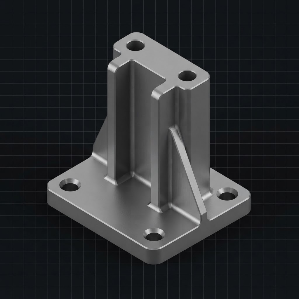
Before · designed for machining
Prismatic form, uniform sections, mass carried where it does no structural work.
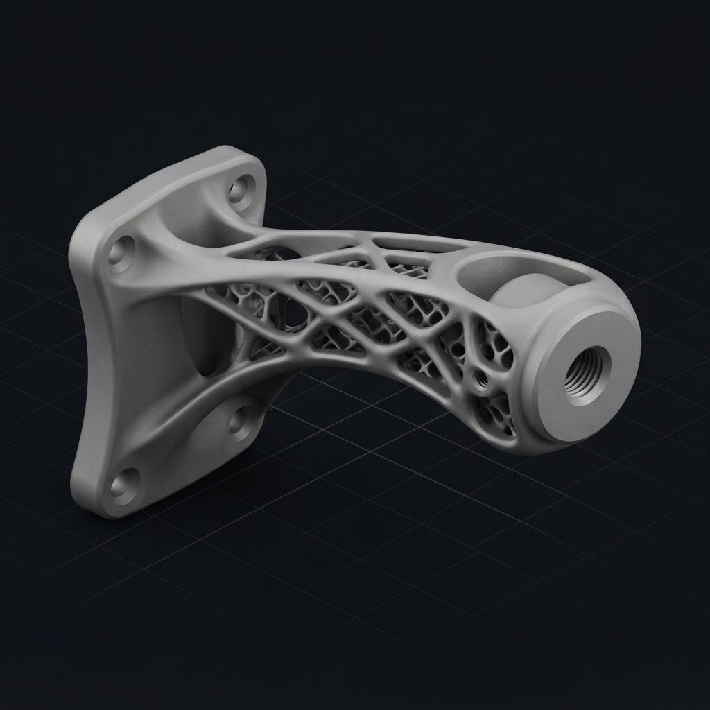
After · designed for additive
Material follows the load path, features consolidated, machining allowance retained on the mounting interface.
Principles
Four principles behind every DfAM review.
Design for the process, not around it
A component drawn for a milling machine carries thick webs, uniform wall sections and features positioned for tool access. Printing that geometry unchanged pays for additive time without gaining anything additive offers.
Decide which features are as-built
As-built accuracy and surface finish are finite. Deciding early which faces, bores and threads must be machined determines where stock is added and how the part is fixtured afterwards.
Orientation is a cost decision
Build orientation changes surface finish, dimensional accuracy, distortion risk, support volume and build time simultaneously. It is chosen deliberately, not defaulted.
Plan the inspection with the design
Datums must exist as measurable features. Agreeing the measurement strategy before manufacture prevents components that are technically correct but cannot be proven.
DfAM capability
What a design review covers.
Eleven areas assessed against your component and its application.
Design optimisation
Reworking geometry around the load path rather than the original machining setup.
Lightweighting
Removing mass where it does no work, while holding stiffness and strength targets.
Lattice structures
Engineered internal structures for stiffness, energy absorption or thermal performance.
Part consolidation
Combining assemblies into a single component to remove joints, fasteners and leak paths.
Internal channels
Conformal cooling and fluid routing that cannot be drilled conventionally.
Build orientation
Orientation chosen for surface finish, accuracy, distortion risk and cost.
Support reduction
Self-supporting angles and access planning to reduce removal cost and surface damage.
Material selection
Matching alloy and process to the mechanical, thermal and environmental duty.
Tolerance planning
Deciding which features are as-built and which must be machined to tolerance.
Machining allowance
Additional stock added at the design stage on faces, bores and threads.
Inspection planning
Datum strategy and measurement method agreed before the part is built.
Next step
Have your component reviewed.
Send the CAD model or drawing. An engineer will assess whether additive is the right route, and what would need to change if it is.